Benefits of Compabloc technology versus shell & tube
Compabloc is a welded plate bloc type heat exchanger technology widely known for its high heat transfer efficiency and compact size. In the past three decades, more than 30,000+ units have been installed globally in various applications like crude oil refinery, oil and gas, petrochemicals, pulp and paper, mining and metal industries, to name a few.
Compabloc technology is widely deployed in crude oil refinery processes like crude oil distillation, alkylation, hydrotreating, isomerization, catalytic cracking, sour water stripper etc. with more than 3000-unit installations, delivering high performance in heat recovery applications, condensers, reboilers and product coolers.
Some of the most widely known benefits of Compabloc's technology over Shell &Tube are:
- High heat transfer efficiency—3 to 5 times heat transfer coefficients compared to shell & tube.
- Compact Size—40,000 ft2 of shell & tube equivalent HTA can be fit in 7 x 7 ft2 of plot space.
- Lower Capex/ Total Installed Cost—Less number of shells, piping, insulation, foundation, valves, instrumentation and smaller structure.
This blog is intended to illustrate how Compabloc technology fares compared to its century old conventional counterpart shell & tube heat exchanger technology. For the purpose of comparison, a design simulation study was made using Alfa Laval’s proprietary design software for Compabloc technology and HTRI design software was used for shell & tube technology. Simulation was made for a typical heat recovery application in crude oil refinery—recovering heat from diesel product from atmospheric distillation column to boiler feed water. Table 1 shows/compares design output on various parameters for both Compabloc and shell and tube technology.
Parameter |
Unit |
Shell & Tube |
Compabloc |
| Application (Heat Recovery) | Diesel Product vs Boiler Feed Water (BFW) | ||
Design Input Parameters |
|||
| Diesel Flow rate | lbs/hr | 355,000 | |
| BFW Flow rate | lbs/hr | 292,000 | |
| Diesel Temp. In/Out | oF | 275 / 79.3 | |
| BFW Temp. In/Out in oF | oF | 70 / 190 | |
| Total Duty | MMBtu/hr | 35 | |
| Max. Design Pressure | psig | 370 | |
| Max. Design Temperature | oF | 350 | |
| Nozzle Size Hot In/Out, Cold In/Out | inch | 6 | |
| Pressure Vessel Code | ASME Sec VIII Div.1 | ||
Design Output Parameters |
|||
| No. of Shells required for Total Duty | 4 in series | 1 | |
| Exchanger Type & Orientation | BEU Horizontal | Compabloc Vertical | |
| Diesel pressures drop | psi | 15 | 17 |
| BFW pressure drop | psi | 13 | 9 |
| Total Heat Transfer Area | ft2 | 17,960 | 3450 |
| Total Empty Weight | lb | 93,120 | 36,300 |
| Total Flooded Weight | lb | 145,400 | 40,800 |
| Tube/ Plate length | ft | 20 | 2.5 |
| Shell OD | Inch | 40 | NA |
| Overall Foot Print for single Shell | ft | 26 x 3.5 x 5.5 | 4.5 x 4.5 x 11.0 |
| (Length x Width x Height) | |||
| Approx. Overall Foot Print for total duty considering 2 stacked shells | ft | 26 x 10.5 x 11.5 | |
| (Length x Width x Height) | |||
| Approx. Total plot space required including maintenance Length x Width | ft | 48 x 12.5 | 7.0 x 7.0 |
| Shell Material | SA516 Gr.70 | ||
| Heat Transfer Material | SA214 | SS316L | |
| Approx. Total Equipment Cost (S&T tubes in CS) | 3.5 X | X | |
| Approx. Total Installed Cost (S&T tubes in CS) | 6 X | 2 X | |
| Heat Transfer Material | SA-249-TP316 | SS316L | |
| Approx. Total Equipment Cost (S&T tubes in SS) | 5.5 X | X | |
| Approx. Total Installed Cost (S&T tubes in CS) | 8 X | 2 X | |
The key takeaways we found when comparing the design output parameters of Compabloc and shell & tube from Table 1 include:
Compabloc needs five times less heat transfer area compared to shell & tube.- Total duty can be performed in single Compabloc shell whereas we will need four shell & tube shells in series.
- Total flooded weight for Compabloc is 3.5 times less compared to shell & tube.
- Total plot space, including maintenance space required by single Compabloc shell, is 12 times smaller compared to 2 x 2 stacked shell and tubes.
- Total installed cost of Compabloc is six times less when compared with carbon steel shell and tube and eight times less when compared with SS tubes in shell and tubes.
To conclude, Compabloc welded plate heat exchanger technology is highly efficient, cost and plot space competitive for high heat recovery duties. We have also seen similar results in condensing applications with close temperature approach. General rule of thumb is: when you are working with two or more shell and tube in parallel/series, plot space limitation, tube metallurgy in higher alloys (eg. Stainless steel) OR when you want to reduce pressure drop, increase process unit capacity in same plot space, debottleneck or improve process efficiency, reduce utilities then you should consider evaluating Compabloc technology. Please contact Alfa Laval’s welded plate heat exchanger technologists for a free evaluation and consultation of your case.
Actual installation comparison between Compabloc and shell & tube
About the author
Sumit Chintawar
Sumit Chintawar is a Refinery Welded Plate Heat Exchanger Technologist at Alfa Laval, working with US refineries to implement welded technology for process reliability and sustainability improvements, also reducing utilities and project capex. Sumit has worked in the refinery Industry for ten years in the Middle East, India and now in the US. He has a Bachelor’s of Mechanical Engineering from Nagpur University, India, and a Master’s in Business Administration from ICFAI Business School in India.
Connect with Sumit on
Why Compabloc?
There are more than 500 Compablocs installed around the world working as cooling water exchangers in crude oil refinery, saving millions of gallons of cooling water every year.
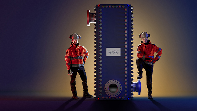
Compabloc liquid-to-liquid
Read other relevant refinery blog posts
How to cut your refinery cooling water consumption by 30-50%
Reduce carbon intensity while improving bottom line in the refining sector
Overcome the challenges of cooling desalter water effluent
Debottleneck naphtha hydrotreaters with highest project ROI
Refinery alternatives to box coolers
Reducing energy consumption in industrial refrigerant systems
Benefits of Compabloc technology versus shell & tube
Using Packinox heat exchanger for catalytic reforming
Efficient wastewater cooling and reuse
Enabling sustainability goals of renewable fuels projects
Reducing scope emissions at refineries: A closer look into utilizing energy efficiency profitably
Energy efficiency opportunities around different heat exchanger positions in a fractionator – Part 1